
The wire library is for the I2C communication between the DS3231 and the Arduino.
Arduino buzzer wiring code#
VCC on the DS3231 to the 5V pin on the Arduinoįinally, connect the positive of the buzzer to pin 11 on the Arduino and the negative the of buzzer to GND on the Arduino.Īrduino Alarm Clock Code #include #include #include LiquidCrystal lcd(2, 3, 4, 5, 6, 7) DS3231 rtc(SDA, SCL) Time t #define buz 11 int Hor int Min int Sec void setup() Code Explanation First of all, we included the libraries for the DS3231 real time clock and the LCD.GND on the DS3231 to GND on the Arduino.Switch DPST Switch DPDT Switch 4PDT Switch Buzzer Crystal Counter (4-bit). Then connect the DS3231 real time clock module to the Arduino as follows: Create electronic circuit diagrams online in your browser with the Circuit.

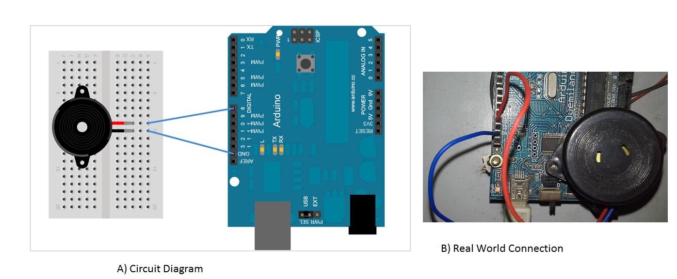
This is the negative pin of the backlight. This is the positive pin of the backlight. Pin 15 to the 5V pin on the Arduino through the 220- ohm resistor.This file contains all the pitch values for typical notes. Click Upload button on Arduino IDE to upload code to Arduino. The code below uses an extra file, pitches.h. Connect the data pins (D4-D7) to the pins 4, 5, 6, 7 on the Arduino. Copy the above code and open with Arduino IDE.Pin 6 on the LCD to the pin 3 of Arduino.Pin 5 on the LCD to the ground of Arduino.Pin 4 on the LCD to digital pin 2 on the Arduino.Pin 3 on the LCD to the middle pin on the 10K potentiometer.Pin 1 on the LCD to ground on the Arduino.Circuit Diagram Connect the LCD to the Arduino as follows: The time and date will also be displayed on the LCD. The beeping time in our code is 2 minutes, but you can increase it as much you want. Connect another jumper wire from a ground pin on the arduino to the upper channel of the breadboard. Wiring schema The connection is pretty easy, it only has control signal and GND. The jumper wires should be connected as follows: Connect a jumper wire from the 5 volt pin on the Arduino to the bottom channel of the breadboard. They can be used in alarm systems, for keypad feedback, or some games. The photo above shows the setup of the project.

The detail instruction, code, wiring diagram, video tutorial, line-by-line code explanation are provided to help you quickly get started with Arduino. Interfacing Buzzer to Arduino: Piezo buzzers are used for making beeps alarms and tones.
Arduino buzzer wiring how to#
If the current time matches with the alarm time, then the buzzer will start to beep. Learn how to use piezo buzzer with Arduino, how piezo buzzer works, how to connect piezo buzzer to Arduino, how to code for piezo buzzer using Arduino, how to program Arduino step by step. We will get the time and date from the RTC module using the library functions and then we will compare this time with the alarm time that we have set in the code. It has a built-in 3V battery, which keeps updating the time. How Does the Arduino Alarm Clock Work? The DS3231 real time clock module keeps track of the time even when the module is not powered.


 0 kommentar(er)
